Time to remove the head. But... we want to be able to put back the head in the exact same way later on.
Otherwise...
So we’ll need to document it well.
The chain you see in the yellow area is the timing belt. This drives the camshaft, which can be seen in the red part.
The belt is fastened to the crankshaft on the underside the engine. The cylinders are also on the crankshaft.
Otherwise...
So we’ll need to document it well.
The chain you see in the yellow area is the timing belt. This drives the camshaft, which can be seen in the red part.
The belt is fastened to the crankshaft on the underside the engine. The cylinders are also on the crankshaft.
This is how it works (in a very simplified way...):
1. the piston goes up;
2. the crankshaft turns and the belt ensures that the red camshaft rotates too;
3. the brown valve rocker pulls open the inlet valve underneath, and a fuel-air mixture flows into the cylinder;
4. the piston goes further upward, the camshaft rotates, the valve shuts, and at (almost) the highest point, the spark plug puts the whole thing on fire;
5. this really shocks the piston ;-) and it’s forced back down by the pressure of the explosion;
6. the camshaft keeps rotating, another valve rocker opens the outlet valve and the burnt fuelmixture flows into the exhaust.
Now is this interesting to know when we want to remove the head bolts?
No, just forget about it.
Yes. Because if the timing belt shifts by just one tooth, the valves open too early or too late and the spark plugs ignite too early or too late.
Result: with one tooth, the engine will probably run joggly. But be ware if the belt shifts by more teeth, because then... nothing will happen: the engine refuses to run.
So what’s the point of this whole story? We’d better make sure the belt is placed over the exact same teeth later on.

So we need to put everything back together in the exact same way. How do we accomplish this?
Here we go.
We place the piston in the first cylinder all the way at the top.
To do this, we go to a wheel at the bottom of the engine that sits on the camshaft. This has a marker.
You can see it here.
The red area shows the crankshaft at the bottom of the engine.
You can see the wheel with the marker in yellow. We used a black marker to make it more visible.
This marker should be at the top. We already placed a big wrench (right) on the nut that’s on the crankshaft.

The wrench on the crankshaft. On the right, the blades of the fan.

The black marker should be precisely aligned with the 0. When that’s done, piston 1 is at the absolute top of the cylinder.

Own idea: to ensure that the belt is placed on the gear in the exact same position later on, we fixed the belt to the wheel with straps (those plastic/elastic straps).

Time to take the gear apart. This will stay behind, while “the head” is taken out along with the camshaft, valves and valve rockers.

The bolt goes off…

Gear is taken off. As you can see, there’s only one way to place it.

A picture of the atmosphere. Click on it to see some more ;-)

Here’s the gear with the chain pulled forward. There’s also only one way to put it back here.
So far, so good...

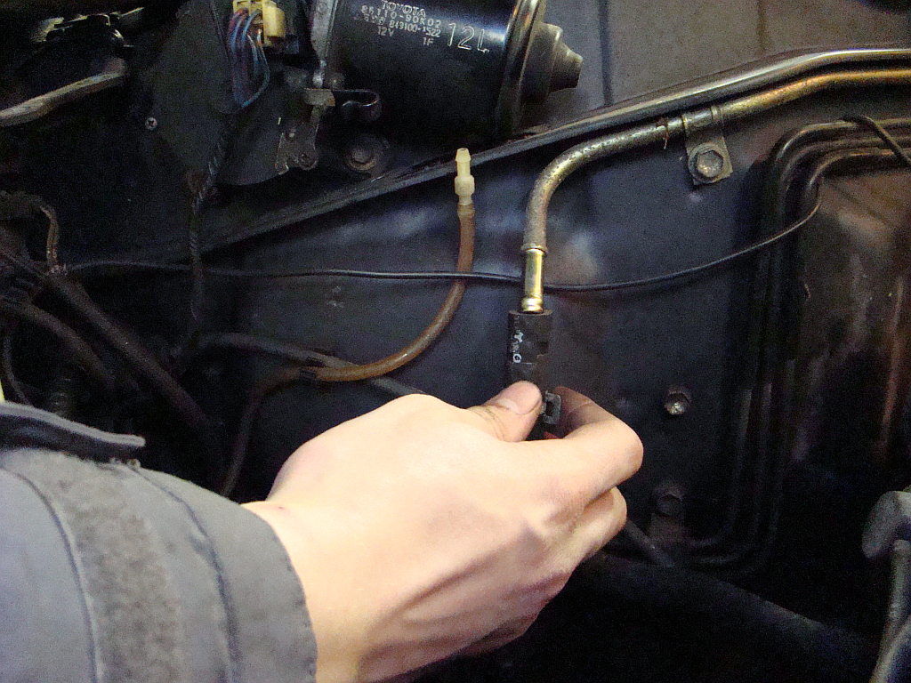
The gas throttle cable runs along the block, so we disconnect it.

...as well as this vacuum hose.

It’s a little tight, but you can just pull the hose off.
Another hose, this is getting a little boring. Just pull it off.

But do NOT forget to label it!

Now to detach a few connectors.

Connectors, connectors and even more connectors. Detach them all after you’ve “lettered” them.

...and another wire. Just pull it loose.

And this is what it looks like after the demolition.

Time to start what we came here for: removing the head bolts. But it must be done carefully. Loosening random bolts will probably lead to a cracked head.
We turn to Toyota for some advice on paper.

We follow Toyota’s wise advice and start on the bolt all the way in front, before the gear even.
The picture isn’t that sharp, but our goal is clear: the bolt in the yellow area.

We work our way from bolt 1 to 10. BUT: we do this in stages. So first you loosen 1 a little bit, then 2, then 3, etc., until you get to 10.
Then you loosen bolt 1 a little more, then bolt 2 a little more, etc.
We did this in three stages.
Here, bolt 1 is being loosened slightly. As you can see we use a solid wrench because the bolts are pretty tight.
Here, bolt 1 is being loosened slightly. As you can see we use a solid wrench because the bolts are pretty tight.

And here we are at number four...

Some of the bolts came off smoothly. The thread looks like this.

But bolt numer 8 wasn’t in the mood. It came out with great difficulty. And so the thread on it looked like this...

Inquiries with Ferry and LandCruiser-forum-Ron (thanks to both!) produced the following recipe for baking such a damaged bolt. Also thanks to Mark for information on the bolts themselves!
One takes a pinch of engine oil, a bit of fuel-air mixture and some drops of coolant.
One presses that together well.
Then one puts it on fire (we hired the spark plug for that :-))
The result is the black gunk you see on the thread.
The result is the black gunk you see on the thread.
And because the head gasket is broken, this also gets to the bolt.
We’ll try to remove it with a bristle.
The screw hole is filled with this deposit. We’re going to twist a tap (which is a sort of bolt with sharp thread on the outside) with the correct external thread in it, in the hope that the gunk will come off...
---more next time---