Sunday, January 16, 2011

Replacing the head gasket, step by step. Part III: Disassembling the Area Around the Head


Disassembling the head. But what exactly is "the head"?
It's the part shown in the following picture.

“The head” consists of several parts:
-         the camshaft. This operates a number of levers (the "valve rockers")
  that...
-         open and close the valves.
-         these valves are in a "cover" that sits on top of the cylinder. This cover
  is called the cylinder head.

Because this is a four cylinder engine there are four covers (cylinder heads) in a row, all in one metal housing..
Which is a little confusing, because this metal housing with the four cylinder heads is called "the head".

We're going to remove the complete head so we can get to the gasket between the "lower block" and the head. The lower block is the part that contains the cylinders and pistons.   

You still with us? :-D
Good, then we can continue with the photo manual.

This is a top view of "the head".
Click a picture to see it full screen.
The colors:
- yellow = the timing belt. We'll see that again later on;
- red = a valve rocker, which is basically a lever that opens and closes a valve.
- blue = two of the ten (actually eleven) head bolts. These are screwed straight through the head into the lower block.
- green = part of the camshaft. The cams move the rockers up and down.
A little more information, this makes it easier to understand what we're doing.
- yellow = the tube through which coolant flows from the radiator to the engine;
- blue = the fuel pump;
- green = the fuel pump's drive: a lever (to the left in the green part) that runs over a wheel which has an opening that's not in the center (for word puzzle lovers: eccentric :-))  This makes the arm move up and down, thus driving the fuel pump. Actually pretty simple, but also quite ingenious;
- red: the aforementioned timing belt.
Next step: disconnecting the three hoses from the fuel pump. All neatly labeled...
Get rid of the supply tube that connects the radiator to the engine.
Unscrew and remove the tube clamp.
Take out the two bolts that connect the fuel pump to the head.
...the fuel pump and lever can now be removed.
As you can see, no more dirt can get under the nails. That space is already full ;-)
...and this is what's left.
An interesting picture, because you can see the ultimate goal of our labor, the head gasket. This is the thin, black line you see in the red circle.
But you also see:
- the fuel hoses are connected to the intake manifold, these stay connected to the head. The fuel lines must therefore be disconnected, which you can see in the yellow "circle";;
- the law of communicating vessels still applies, which is why coolant keeps dripping from the engine. This happens in nice, separate drops that you can see in the green area.

Now it's time to disconnect the bypass hose (in yellow): when there's no need for cooling, the coolant immediately flows back to the radiator..
To remove: unscrew the hose clamp and pull the tube off while twisting simultaneously.
The green part is the intake manifold.
And then we got tired of the coolant's constant dripping. So we drain it the LandCruiser way: open the tap and let it flow. Nice and simple.
Time to take a break and have a look at the joint packing. That's a lot.
And this is our "objet du désir" (object of desire): the new head gasket.
The accompanying description provides valuable information, including the cylinder diameter (92 mm), order in which the head bolts need to be tightened, and torque. More on that later.
Click the picture for a (very large) magnified view.
Meanwhile, there's still something in our way on the right side of the engine block: the power steering pump (in yellow). We'll have to take it off.
By unscrewing this bolt you can detach the pulley (= wheel with a notch for the V-belt on the outside) and move it to the right, so the V-belt that runs over it can be removed.
Then the bolts are removed from the power steering pump, and the pump can be taken out in its entirety.
This can be seen here.
Now it's the exhaust's turn. A manifold is attached to the right side of the head. Each cylinder has its own exhaust and the exhaust manifold turns the four pipes into one. This is the exhaust...
The exhaust manifold (the red part shows the connection to the head) is a little bit hot, so a sort of shield is placed in front of it: a heat shield (yellow).
The heat shield (yellow) is disconnected. The manifold is visible in all its glory.
By twisting the nuts off the manifold, you can pull the manifold forward.
---more next time---

Saturday, January 15, 2011

Replacing the head gasket, step by step. Part II: The Valve Cover.

The next step in replacing the head gasket or replacing the head: removing the valve cover.

We'll need to remove a few things first.
Starting with the distributor and the spark plug wires.

The spark plug wires are up first. We've learned from our earlier experiences with S's Porsche 924, and label the connections and cables well before we get started.
An overview picture.
A convenient distributor which is already numbered.
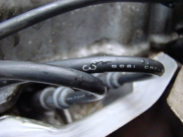
Even the spark plug wires have numbers.
Just to be sure, we number the spark plugs anyway. Little extra work, and saves a lot of time when reconnecting.
...and the spark plug wires can be disconnected.
The cable from the contact points to the ignition coil. Everything was thought through on this Toyota. The cables are fitted with a watertight plug and socket and are easy to disconnect.
Here's a (green) plug-socket.

Plug out of the ignition coil (right side).
Take out the dipstick.
The vacuum hoses have been labeled and are taken off the distributor.
The distributor housing can be rotated slightly to delay or speed up the ignition timing. This has been marked here.
Bolt number 1 on the distributor is loosened.
After the bolts have been loosened, the whole distributor can be pulled out.
This is what the distributor's drive shaft looks like.
To prevent dirt collection, a clean cloth is placed in the opening.
The hose for the oil supply at the valve cover is loosened and removed.
The gas throttle cable is removed from the support on the valve cover.
The four bolts on the valve cover are loosened and removed.
The rubber rings seem to be stuck quite nicely. We were able to remove them by pulling upwards while twisting.
And... the valve cover can be lifted off!
This is what the top looks like. Click the picture to view it in full screen.
---more next time---

Replacing the head gasket, step by step. Part I: The Air Inlet.

This is our story about overhauling a 22R petrol engine of a LandCruiser LJ70.

Warning
Please note:
1. We are not professionals, we're amateur mechanics. This is our first time doing this, so there may be some mistakes in the description that follows.
2. It's extremely useful to have a shop manual for this type of engine.

Why?
The exhaust of the LandCruiser RJ70LV we purchased blows out large clouds of white fumes. If you put your hand in the fumes at some distance, it'll be wet and smell like coolant.
After reading through lots of forums, it seems there are two options: either the head gasket is broken, or - even worse - a broken head.


We decided to fix this ourselves, and this is our accompanying report. It is a step by step photo report.

For whom?
We only have limited experience in tinkering with cars. This report would be well suited for a recently started amateur.
On the other hand: I'm doing this with my son who is a second year Automotive student at an Institute of Technology, so that helps.
The photos are step by step. Too detailed? Feel free to skip ahead.

Which engine?
The engine we're working on is a 2.4 liter Toyota LandCruiser gasoline engine. A straightforward 4 cylinder in line. The engine is a type 22R.
This report seems suitable for all 4 cylinder line engines, but with a side note that all photos are of a 22R engine.

What do you need?
Because of my occupational disability (I am a Project Manager), the first thing I want to know is: what do I want to achieve?
In this case that would be: how do I get from…
A: a defective engine with clouds of white exhaust fumes,
to
B: me behind the wheel with a smile on my face and a street behind me that isn't white from all the fumes.

First we'll need the correct information (yup, I'm Project Manager in Automation).
We found this in two books. You can see them both in a previous part of this blog.
The “Toyota 21R, 22R Engine repair manual” from 1987 has the most information.

The steps
We'll need to execute the following steps  to get to the cylinder head (source: the Toyota 21R, 22R Engine repair manual).
This is just an outline. We'll use photos  to illustrate what we're doing
later on.
1.      preparation
2.      remove everything above the engine, i.e. the air filter;
3.      remove dipstick, distributor and spark plugs;
4.      remove valve cover;
5.      remove fuel pump and related connecting tube;
6.      remove water hose from intake manifold;
7.      set cylinder no. 1 at top dead center, which is done by placing a mark
    on  the crankshaft;
8.      put a marking on the timing belt so it can be put back into the exact
    same position later on.
    Also remove sprocket which runs over the timing belt.
9.      remove cylinder head itself. The bolts need to be removed in a certain
         order.

Tools
So far, we've determined that we'll need:
-         the right wrenches;
-         a torque wrench so the bolts can be tightened with just the right force;
-         a scraper to scrape away the old head gasket;
-         a new head gasket of course, and other gaskets to put everything back together;
-         a flat straight-edge (sort of ruler) to see if the gasket is still level, and a feeler gauge to measure any eventual space under the straight-edge. We'll try to make do with the flat side of a level for the time being;
-         a spray to spot cracks in the cylinder head;
-         undoubtedly, the more standard tools such as screwdrivers and pliers;
-         As far as I can tell, no exotic tools will be necessary.

Preparatory work:removing the air filter
We could write down exactly what we did, but pictures say a whole lot more, I think.
Hence the following step by step photo report. A lot of the pictures are a little grainy, which is not so nice, but there was very little light. The flash option gave shadows.

Clicking a picture makes it full screen.

The place where it's all going to happen:
The bonnet is in the way, but we can remove that by unscrewing the four bolts. We'll do that :-)
On the left side you'll see the sticker with the Landcruiser type on it: RJ70
Not a lot of space for the parts, but it's usable.
May come in handy later, hence the picture.
"Vacuum hose information".  A schematic of how the vacuum hoses are connected. No idea what it's for yet, but we'll see.
No bonnet. That creates space. And light!
Remove the voltage first.
And disconnect the positive pole. The red wire leads to...
...a battery charger. This LandCruiser is from Sweden where it's useful to always have a fully charged battery at low temperatures.
Time for the manual.
Which includes: "how to remove a cylinder head".
Detach the end of the air filter.
You can store the loosened bolts separately of course. We leave them in the right place whenever possible. Saves us from search work later on.
Next step: disconnect the connector from the air filter.
We found this on the under side of the air box's filter (the large round biscuit tin).
This is part of the EGR (Exhaust Gas Recirculation). T. - the Automative student - knew exactly what it was (and so did Wikipedia, read this).
My conclusion: not good, replacement necessary.
Loosen the left fastening screw.
Pull the tubing at the top.
Loosen the tube at the top of the air drum - engine.
Unfasten the air filter's cover.
Remove the clamps.
Remove the cover.
Loosen bolt on right side of the air filter housing.
Remove tubing underneath (pull).
...and the whole air filter box can be removed.
This is what the top looks like.
---more next time---